This is a tutorial on how to implement Pulse Width Modulated (PWM) in Raspberry Pi 2 and 3 using Python.
Since the Raspberry Pi 3 uses the BCM2837 and currently I could not find the specification sheet of BCM2837. I shall assume that the GPIO for the BCM2837 and the BCM2835 (Pi 2) are the same since the Pi 2 and Pi 3 Model B looks the same. I will use the Specification Sheet of the BCM2835 for reference.
I’ll check slowly check if there’s a difference among the two in terms of GPIO.
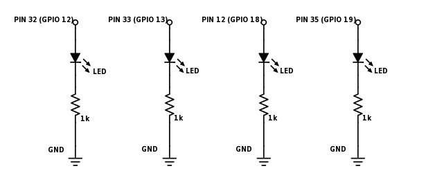
PWM GPIO Pins and Channels
Only 4 GPIO pins are available for PWM in the Raspberry Pi if we base it on the data sheet of BCM2835. And only 2 channel PWM are available (PWM0 and PWM1).
| BCM2835 Specification Sheet (PWM) | |||
| PWM0 | PWM1 | Raspberry Pi 3 GPIO Pin |
|
| GPIO 12 | Alt Fun 0 | – | Pin #32 |
| GPIO 13 | – | Alt Fun 0 | Pin #33 |
| GPIO 18 | Alt Fun 5 | – | Pin #12 |
| GPIO 19 | – | Alt Fun 5 | Pin #35 |
| GPIO 40 | Alt Fun 0 | – | N/A |
| GPIO 41 | – | Alt Fun 0 | N/A |
| GPIO 45 | – | Alt Fun 0 | N/A |
| GPIO 52 | Alt Fun 1 | – | N/A |
| GPIO 53 | – | Alt Fun 1 | N/A |
PWM Channels Clarification
I assumed at first when changing the duty cycle or the frequency of GPIO 12 (Pin#32) it would automatically change the duty cycle of the GPIO 18 (Pin#12) but it did not. Both PWM pins acted independently from each other.
I have to read more about the PWM Channels.
Python Functions
Below are the list of Python functions for using PWM in Raspberry Pi.
p = GPIO.PWM(pin, freq) |
pin – pin number/GPIO number
|
Creates an PWM instance and assigns it to variable p |
p.start(dutyCycle) |
dutyCycle – Starting duty cycle
Values from |
Starts the PWM |
p.ChangeFrequency(freq) |
freq – new Frequency in Hertz |
Changes the frequency of the PWM |
p.ChangeDutyCycle(dutyCycle) |
dutyCycle – new duty cycle
Values from |
Changes the duty cycle of the PWM |
p.stop() |
Stops the PWM |
Examples
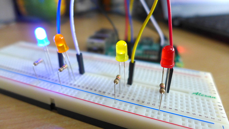
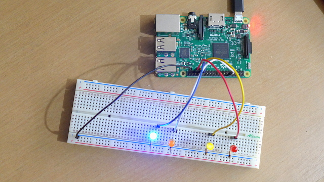
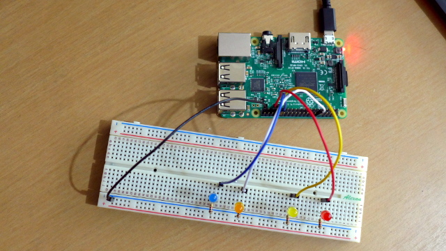
Here’s my setup for the following examples.
Example #1 of 2:
Testing the 4 PWM pins based on BCM2835 data sheet.
import RPi.GPIO as GPIO

GPIO.setmode(GPIO.BOARD)

# Setup GPIO Pins
GPIO.setup(12, GPIO.OUT)
GPIO.setup(32, GPIO.OUT)
GPIO.setup(33, GPIO.OUT)
GPIO.setup(35, GPIO.OUT)

# Set PWM instance and their frequency
pwm12 = GPIO.PWM(12, 0.5)
pwm32 = GPIO.PWM(32, 0.75)
pwm33 = GPIO.PWM(33, 0.66)
pwm35 = GPIO.PWM(35, 0.87)

# Start PWM with 50% Duty Cycle
pwm12.start(50)
pwm32.start(50)
pwm33.start(50)
pwm35.start(50)

raw_input('Press return to stop:')	#Wait

# Stops the PWM
pwm12.stop()
pwm32.stop()
pwm33.stop()
pwm35.stop()

# Cleans the GPIO
GPIO.cleanup()
Check the video below to see the result of Example 1.
Example #2 of 2:
Changing the duty cycle of each PWM Pin. The LED would brighten up and then dim down.
import RPi.GPIO as GPIO
import time

GPIO.setmode(GPIO.BOARD)

# Setup GPIO Pins
GPIO.setup(12, GPIO.OUT)
GPIO.setup(32, GPIO.OUT)
GPIO.setup(33, GPIO.OUT)
GPIO.setup(35, GPIO.OUT)

# Set PWM instance and their frequency
pwm12 = GPIO.PWM(12, 60)
pwm32 = GPIO.PWM(32, 60)
pwm33 = GPIO.PWM(33, 60)
pwm35 = GPIO.PWM(35, 60)

# Start PWM with 50% Duty Cycle
pwm12.start(0)
pwm32.start(0)
pwm33.start(0)
pwm35.start(0)

try:
  while True:
    for dutyCycle in range (0, 100, 5):
      pwm12.ChangeDutyCycle(dutyCycle)
      pwm32.ChangeDutyCycle(100-dutyCycle)
      pwm33.ChangeDutyCycle(dutyCycle)
      pwm35.ChangeDutyCycle(100-dutyCycle)
      time.sleep(0.1)

    for dutyCycle in range (100, 0, -5):
      pwm12.ChangeDutyCycle(dutyCycle)
      pwm32.ChangeDutyCycle(100-dutyCycle)
      pwm33.ChangeDutyCycle(dutyCycle)
      pwm35.ChangeDutyCycle(100-dutyCycle)
      time.sleep(0.1)

except KeyboardInterrupt:
  pwm12.stop()
  pwm32.stop()
  pwm33.stop()
  pwm35.stop()

# Cleans the GPIO
GPIO.cleanup()
Check the video below for the results of Example 2.
Testing on non-PWM pins
I was curious if I run the PWM code on a non-PWM pin would it work or not, so I ran some tests. Specifically on Pin #8 (GPIO 14) and it turns out that you can still run the PWM Code even if the pin does not have a PWM alternate function.
Here is the code that I used.
import RPi.GPIO as GPIO

GPIO.setmode(GPIO.BOARD)

# Setup GPIO Pins
GPIO.setup(8, GPIO.OUT)

# Set PWM instance and their frequency
pwm8 = GPIO.PWM(8, 0.5)

# Start PWM with 50% Duty Cycle
pwm8.start(50)

raw_input('Press return to stop:')	#Wait

# Stops the PWM
pwm8.stop()

# Cleans the GPIO
GPIO.cleanup()
Note: I also tried in Pin 19 (GPIO 10) and the PWM is still working. Check the video below.
I think it is safe to say that the PWM works on all other GPIO pins.
Note: Do you now how frustrating it is to read through the specification sheet to make sure what are the PWM pins, only to know that they are working through out all the other pins?
This makes me wonder if the Python PWM of the Raspberry Pi is a Hardware PWM or a Software PWM.
If the Raspberry Pi Python PWM is a software PWM then is the Raspberry Pi PWM trustworthy enough to produce the correct PWM Signal or will it be affected by other programs that are fighting for processing time in the CPU?
I need to do more research and tests on this.
If you have suggestions or additional knowledge about the PWM of Raspberry Pi, kindly comment below.
Python RPi.GPIO use only soft PWM.
So your testing codes are all soft PWM, not H/W PWM.
So you can use any GPIO pins for soft PWM.
Thank you for the verification Seunghyun Lee! ^_^
three are three different kinds of PWM with the Pi:
– timed by peripherial hardware on specific pins (12/18, 13/19)
– timed by DMA (direct memory access) -> bus-clocked; not as flexible but still precise
– software timed by operating system (flexible but imprecise, unsuitable for servos)
good reading from the author of pigpio:
https://raspberrypi.stackexchange.com/questions/100641/whats-the-difference-between-soft-pwm-and-pwm
It really depends on which library you rely on (RPi.GPIO, pigpio, wiringpi-python..)
Not sure why but nothing happens with motors when program runs. No error messages. Spent about 200 hours trying to get this to work. Best instructions yet, official pi instructions results in fire…
Hi Lon, not sure about your setup but a couple of questions to guide you.
Is the PWM working when you attach an LED to it (without the motors)?
If yes, do you have a motor driver between your Raspberry Pi and Motor?