I wanted to know the Schmitt Trigger Voltage Logic Levels for the Arduino Uno since I want to know on what voltage would the digital input pin detect a logic high or a logic low.
I know that the Arduino Uno uses the ATmega328 with a 5V as its voltage supply. I checked the ATmega328 specification sheet and since it was too long to read (TL;DR), I would rather check using a Signal Generator and an Oscilloscope.
- The Setup
- Oscilloscope Graph (Voltage-Time)
- Oscilloscope XY Graph (Input, Output Voltage)
- Arduino Uno Schmitt Trigger Voltage Levels
- Improvements
The Setup
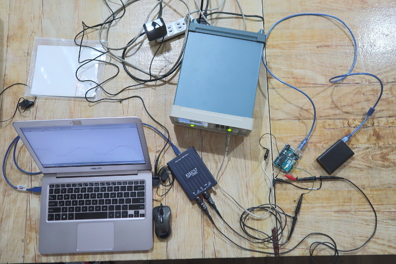
Here is the list of equipment that I used for doing this experiment
- Arduino Uno powered via USB port
- Laptop (Windows)
- 2-Channel Oscilloscope (PicoScope)
- Signal Generator
Arduino Sketch
#define PIN_INPUT 2
#define PIN_OUTPUT 3

void setup() {
  pinMode(PIN_INPUT, INPUT);
  pinMode(PIN_OUTPUT, OUTPUT);
}

void loop() {
  boolean inputValue = digitalRead(PIN_INPUT);
  digitalWrite(PIN_OUTPUT, inputValue);
}
The goal of the code above is to reflect the state of the digital input pin to a digital output pin. See below.
- Input: Voltage Threshold Reached for High
Output: Digital High (5V) - Input: Voltage Threshold Reached for Low
Output: Digital Low (0V)
This way we could determine whether the Arduino Uno digital input pin is registering a high or a low and see it in the Oscilloscope.
You can get the code on my Github here.
Signal Generator Settings
- Waveform: Triangular Wave
- Frequenzy: 10 Hz
- Highest Voltage: 5V
- Lowest Voltage: 0V
The goal of the Signal Generator is to generate a linear signal (rising and falling) with a slow enough frequency for me to determine when the Arduino Uno sees the voltage level is a high or a low.
Having a higher frequency would be generating enough delays compared to the period of the frequency making me not determine the correct voltage thresholds.
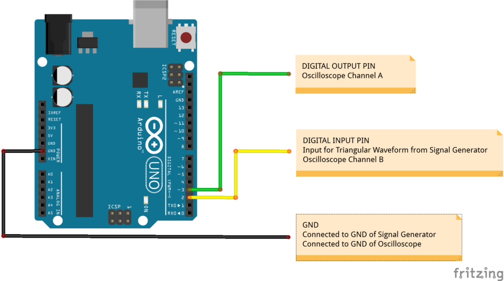
Fritzing Diagram
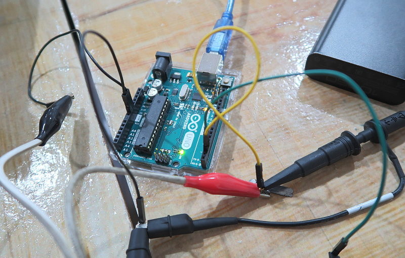
Since my photo of the setup that I had is a bit messy, here is a Fritzing Diagram on how I connected the Arduino Uno to the Signal Generator and the Oscilloscope.
Oscilloscope Graph (Voltage-Time)
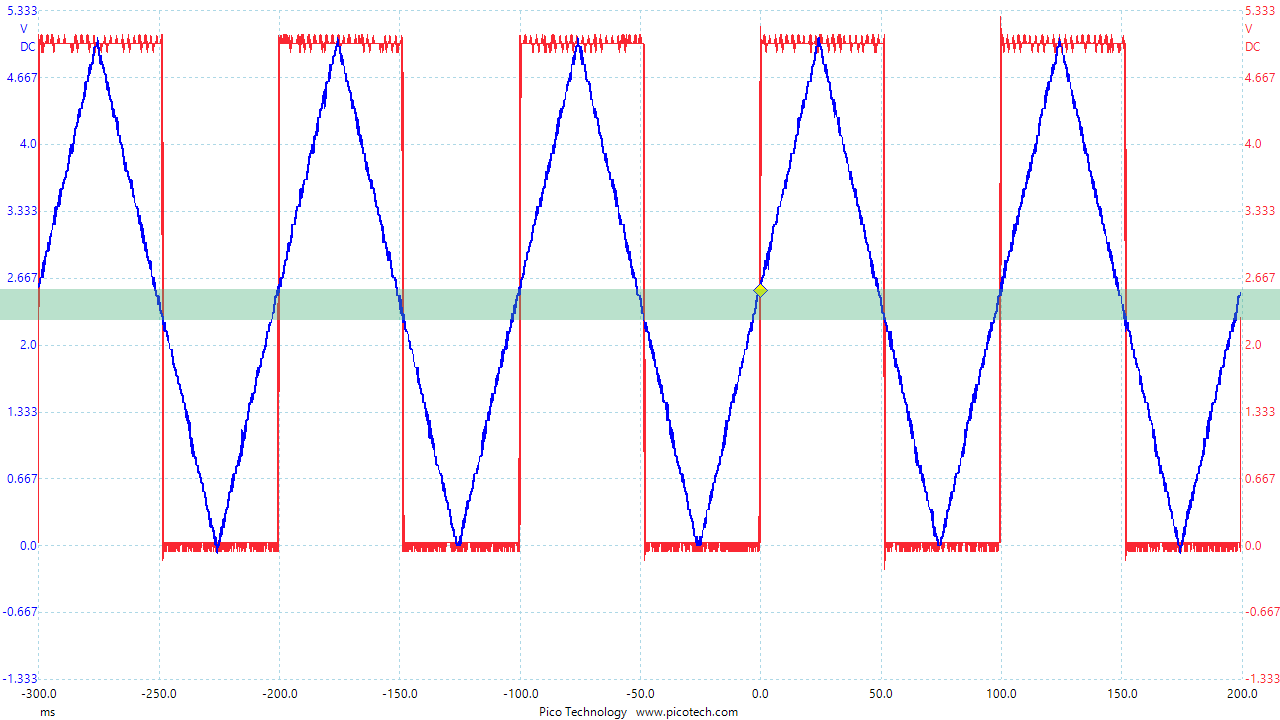
Below is the Oscilloscope Graph given the setup above.
- Input: Blue (Triangular Waveform)
- Output: Red (High or Low)
As expected the when the triangular waveform hits around 2.5V there is a change of state on the output. But I have to determine on what conditions does the Arduino detect a change of state in the input.
I measured and these are the result and their conditions.
| Input State Detect | Waveform State | Voltage Level |
| LOW | Falling | 2.2V |
| HIGH | Rising | 2.6V |
Note: Voltage Levels are just approximations. I would love to go down to the millivolt to get a more exact threshold voltage but I need to do another experiment for that. See improvement #1.
Since the voltage levels and the waveform state is different for the change of state of the digital input pin of the Arduino Uno, we can say that there is hysterisis and we can conclude that the Arduino Uno or the ATmega328 has a Schmitt Trigger in its digital input pins.
See the green area below.
Oscilloscope XY Graph (Input, Output Voltage)
The hysterisis is more obvious when I set the Oscilloscope on an XY Graph.
- X-axis: Input (Triangular Waveform)
- Y-axis: Ouput (High or Low)
Below are zoomed in versions of the graph above with the Schmitt Trigger Threshold Voltages.
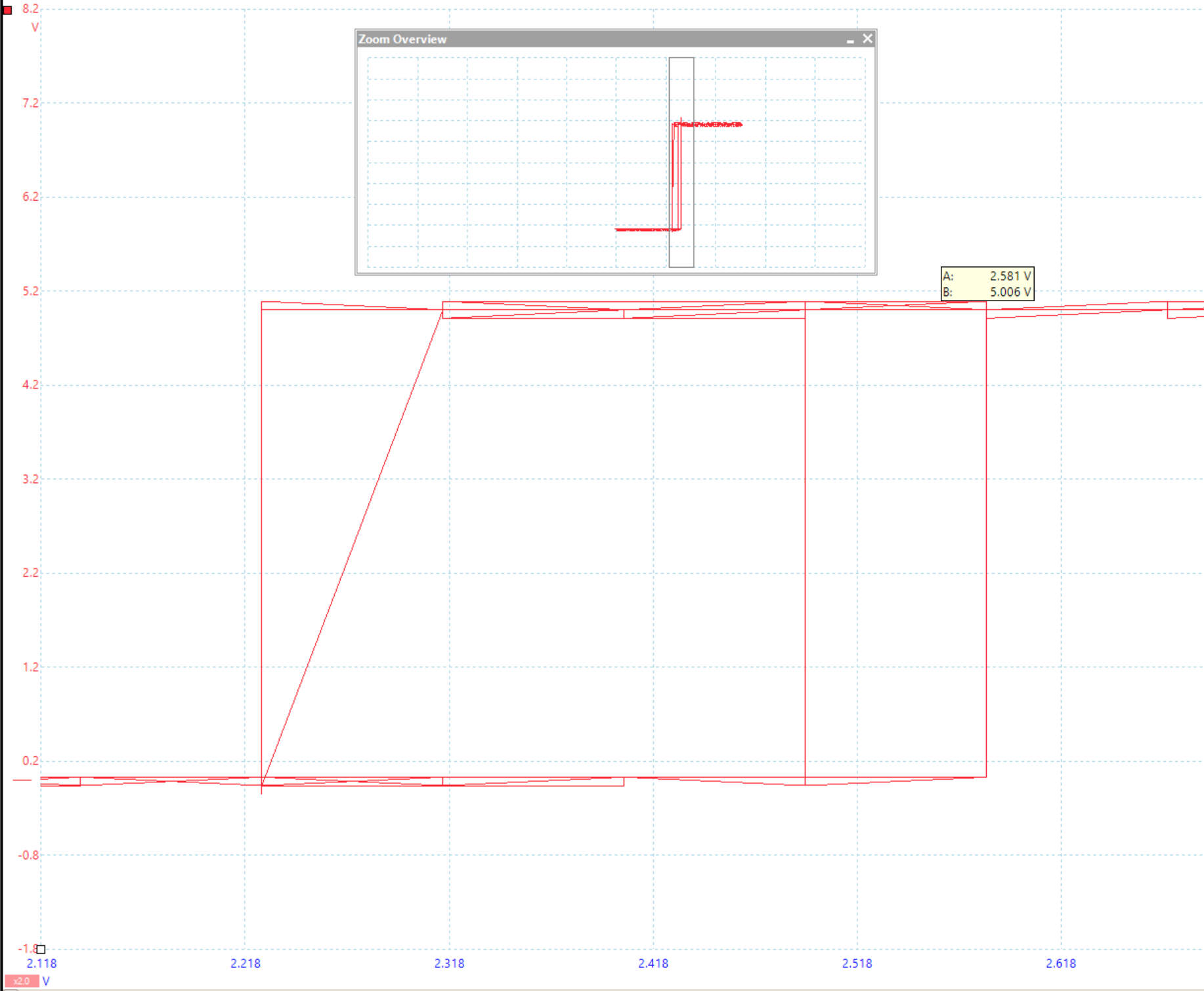
Input: 2.581V
Ouput: 5.006V
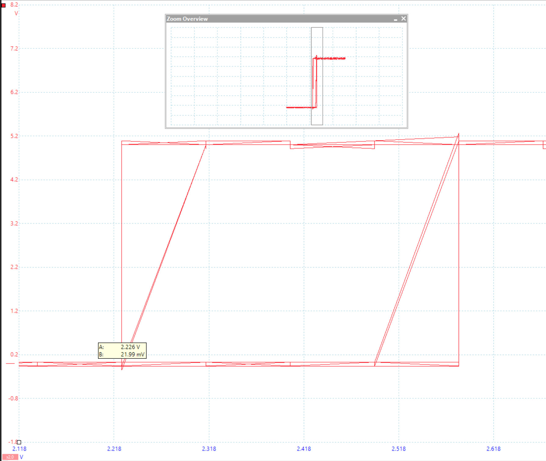
Input: 2.26V
Ouput: 21.99mV
Note: I need to know what makes the XY graphs not show a perfect rectangular shape but shows some lines in between. I am thinking that this is caused by delays by the processing time of the ATmega328. See improvement #3.
Arduino Uno Schmitt Trigger Voltage Levels
In summary, the Arduino Uno or ATmega328 uses Schmitt Triggering for its digital inputs.
The following are the conditions for the digital input pin to determine whether it detects a HIGH or LOW when the Arduino is powered via the USB port.
| Input State Detect | Voltage Level |
| Logic LOW | less than 2.2V |
| Logic HIGH | more than 2.6V |
Additional Note: Since the Arduino Input Digital Input will detect HIGH when the voltage applied to the pin is more than 2.6V and the Raspberry Pi digital pin output HIGH is 3.3V, I could now confidently say that we could interface an output pin of the Raspberry Pi to an input pin of an Arduino Uno.

Improvements
Here are some room for improvements that I need to do to get a better grasp on the Schmitt Trigger Voltage Levels of the Arduino Uno.
(1) I just realized that I could use a 12-bit Digital-to-Analog Converter and use it make triangular waves while checking for the Schmitt Trigger Voltage Levels of the Arduino Uno.
I am targeting this guy, MCP4725 Breakout Board – 12-Bit DAC w/ I2C Interface. With this I could determine the Threshold Voltages with a step of around 0.244 mV, better resolution than my eyes could see in the oscilloscope.
(2) I also need to check each pin, maybe they have different Schmitt Trigger Voltage Levels.
Another scenario would be to check the Logic Levels when the power source is from the DC Power Jack or Vin.
(3) I need to check on what makes my Oscilloscope XY Graph not perfect and improve it. Maybe this is due to the delays in the processing of the microcontroller. Or maybe the RAM is already full and needs to clear up some space before it could continue processing. Anyways, need to do more experiments on this.
(4) I shall also be doing this on a Raspberry Pi and on different boards that use different microcontrollers.
If there are still some improvements you think I can still do or if you see errors let me know on the comments below.
Good test method and a nice job. Your results are consistent with the graphs in the data sheet, which show how the trigger levels relate to supply voltage and temperature.
Thank Scott!
was awesome
Thanks for your analysis, it saved me some time. While there is some hysteresis, .4 V is not very much by comparison to some common hex inverter ICs, which is what I wanted to know. The common CD40106B is .9 V hysteresis, while the 74HCS14 is .6 V.
Thanks for the thorough demonstration.
I am new to this. I have a 74AC14 (in a tdr circuit) that outputs a reflected wave and want to use Nano to find the amplitude and frequency of the wave. What will be the schematic?